 |

 Overview Overview
 Specifications
(Features) Specifications
(Features)
 Implementation
Notes Implementation
Notes
 Pricing Pricing
|
REPLACED BY 5R7-570
Overview
The Model 5C7-550 series is an economical, open board
temperature controller
especially designed to operate thermoelectric (Peltier effect) modules.
This controller will provide temperature control of thermoelectric
modules
up to 350 watts (28vdc X 12.5 amps = 350 watts). They use a
 TR67
Series temperature sensor for a temperature range of -20°C
to 100°C, or a
 TR104
Series temperature sensor for a temperature range of 0°C
to 150°C. The sensor selection
is made via a PCB mounted dip switch.
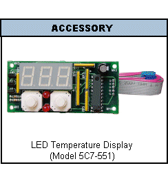
The Model 5C7-551 remote digital temperature display (shown
above
left) is compatible with the Model 5C7-550. The 5C7-551 is
provided
as two separate pieces: a PCB, ribbon cable. Up and down buttons are
used
to set the Set Point temperature, and set the temperature scale (units)
of Celsius or Fahrenheit. Normal display mode shows the actual
temperature
read from the control sensor. Displayability is 0.1 for temperatures
from
0.0 to 99.9 degrees, and otherwise is an integer value. You can also
order
the optional P/N 5C7-553 for the mounting plate..
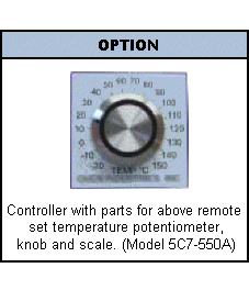
The Model 5C7-550A is an optional version of the
controller that
includes a remote set temperature adjust dial (shown above right). The
dial is provided as two separate pieces: a potentiometer that has leads
and a connector, and an adhesive dial scale decal. (You can also use
the
optional Model 5C7-551 to view the actual temperature while using the
potentiometer
based dial to set the Set Point. In this combination with the 5C7-550A
the 5C7-551 is only used to display the actual temperature.)
The controller contains a solid state “H” bridge. This
provides bipolar
(BI-directional, automatically heating and cooling as needed) control
for
one or more independent TE modules for both cooling and heating
applications.
With appropriate diodes, it can be used in conjunction with auxiliary
or
supplemental resistive heaters. The control of the “H” bridge is
designed
to provide a seamless transition between heating and cooling. (no dead
spot in the control function during transition between heating and
cooling)
The controller utilizes Pulse Width Modulation (PWM) to
control the
power level in the thermoelectric module. The base frequency is 1.0kHz.
The output power resolution is one of ± 250 steps in the load
circuit
control.
The controller provides an indication of the heat or
cool operation
mode. A Green LED is used to
indicate
a heating mode. A Blue LED is used
to indicate a cooling mode.
Both the Green and Blue LED being on indicate an open
sensor. The controller
load circuit (output power) is off when there is an open sensor.
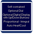
This controller was designed with a proportional and
integral control
algorithm to provide the most precise control at the most economical
cost.
The proportional bandwidth is adjustable from 1.0°C to 16°C and
the integral rate is adjustable from 0 to 2.55 repeats per minute.
These
adjustments permit optimizing individual thermal systems. In a well
designed
thermal system end point control can be ± 0.1°C.
The controller is capable of providing up to 12.5 amps
of current for
modules rated 3 through 28 volts dc with an ambient temperature of
0°C
to +50°C. (refer to mounting instructions)
The controller will operate with a single power supply
over the range
of 6vdc to 28vdc. If the TE modules require lower voltages, then two
supplies
are required. One supply for the load 3vdc to 28vdc and one for the
control
circuit 6vdc to 28vdc (the control circuit will draw less than 100ma).
The controller electronics have a set point stability of
< ±0.1°C
after one hour of stabilization at 25°C ambient.
The controller has a temperature resolution of
approximately 0.1°C.
In an optimal thermal system, this will provide an end point control of
up to approximately ±0.2°C, or slightly better. To achieve
this
control requires that the thermal system be well designed, the control
sensor be correctly located, and the system be optimally tuned. When
selecting
the temperature sensor location, we suggest that the sensor be located
thermally close to the working side of the TE module. Minimum delay in
the temperature sensor seeing the temperature change in the TE Module
temperature
is preferred.
 Mechanical
Specifications
Note: For a small but intelligent TEC
controller with either
heat only or automatic bi-phase heat and cool, consider a customized
version
of a 5R7-001 Series controller. For an NRE,
we can provide custom, PC compatible controllers with a much smaller
footprint
than our standard controllers. Interfaces include RS485, RS232, and
I2C.
The interface is used to set up the controller or to monitor the
temperature.
Otherwise, a configured controller can run standalone.


- LOAD:
Compatible
with Thermoelectric
(Peltier effect, or TEC) modules, resistive heaters, fans, and many
other
DC voltage devices that proportionately alter operation based on the
amount
of power supplied.
- STABILITY: The
controller itself has
an internal resolution of approximately 0.1°C, and that means the
best
attainable stability is approximately 0.2°C or better.
Stability
is intimately related to your thermal system. If you are not seeing the
stability your application requires, we can, for an NRE, build a custom
unit. We have many ways to adapt this controller to your requirements
and
to the specific parameters of your thermal system.
- OUTPUT
- Biphase: Automatically switches between HEATING and COOLING modes. (For resistive heaters and fans
place
an appropriate diode in series with the load.)
- PWM: Pulse width modulated output with a
base
frequency of 1.0kHz
- Proportional / Integral
Control Algorithm
- Proportional Bandwidth: Adjustable or
fixed
proportional bandwidth
of 1°C to 16°C using an on board potentiometer.
- Integral Gain: Adjustable or fixed
integral
rate of 0 to 2.55 repeats
per minute (also known as "sample rate".) using an on board
potentiometer
- Power
- Using Single Output Power Supply: Rated
for
±1.0 amperes
to ±12.5 amperes at 6 to 28 volts DC..
- Using Dual Output Power Supply (or 2
supplies):
Less than 500 ma
at 6 to 28 vdc is needed for the control circuit. Power supply for the
load can be 3 to 28 vdc at 12.5 amperes maximum.
- Ouput Power: 350 Watts Total Maximum.
- TEMPERATURE
- Range of 5C7-550 &
5C7-550A
-
 TR67
Series, 15K@25°C: -20.0°C
To 100.0°C (-4°F
to 212°F)
-
 TR104
Series, 50K@25°C: 0.0°C
To 150.0°C (32°F
to 302°F)
- Adjustment:
The 5C7-550 has an
on board potentiometer, or, optionally, the 5C7-551 front panel PCB
(see
"accessory" above). The 5C7-550A
has
a potentiometer/dial combination (see "option" above),
or you can unplug that from the controller and in its place use the
5C7-551
front panel PCB (see "accessory" above).
- Operation
- Ambient Operating
Temperature
- 0C to +50C for
off-the-shelf controllers.
 Notes
on Ambient Operating Temperature
- Connections:
Pluggable barrier strip
with screw down connections.
- Dimensions:
 Mechanical
Specifications
- Production Models:
Once the controller
is configured for your application we provide services that can lower
the
cost and simplify configuration, production, and distribution.
Full featured / Low Cost.
Implementation Notes
 Mechanical
Specifications
For general information about power supplies see our
Library page: Power
Supply Notes.
MULTIPLE SET POINTS: Since the temperature is set
using a potentiometer,
and the heat and cool mode is determined by a jumper, it is relatively
easy to make a circuit that allows you to easily switch the Model
5C7-550A
between two or more temperature settings.
FOR FIBER OPTIC COMPONENTS AND LASER DIODES...
 Note.
Note.
Pricing
Note: Prices shown are for the
controllers only.
Sensors, TE modules and power supplies may be available but are not
included
in the controller pricing.
Lead Time: Generally 2 to 4 days
ARO. Out of stock
items may have a 1 to 3 week lead time.
SENSOR PRICING
 Click
here for TR67 Series Sensor Housings and Prices (-20°C
to 100°C Range)
 Click
here for TR104 Series Sensor Housings and Prices (0°C
to 150°C Range)
Model
5C7-550 Temperature Controller
Lower prices
are available at higher volume.
Model
5C7-550A Temperature Controller with Remote Potentiometer
Lower prices
are available at higher volume.
Model
5C7-551 Front Panel PCB
Note:
Does not include metal face plate or label.
You
can use this with the Model 5C7-550 controller.
You
can use this with the Model 5C7-550A, but only if you unplug
the
potentiometer based dial.
Lower prices
are available at higher volume.
P/N
5C7-553 Mounting Plate (for the Front Panel PCB)
Note:
Does not include label.
Lower prices
are available at higher volume.
- General
Notes on Pricing of the above controllers.
- Controllers
Only: Prices shown are for the
"controllers
only".
- Currency:
All prices are $US.
TEMPERATURE SENSORS
Ohms@25°C
THERMISTOR SERIES
•
•
•
•
•
•
•
•
•
•
•
RELATED SENSOR PAGES
•
•
•
DESIGN & MANUFACTURING
•
•
With our RS485/RS232 interface you can run any RS485 device off your computer's serial port (the RS232 COM port). Our interface is an opto-isolated "Automatic Transmit-Enable" converter (°3000VDC, 1 second). This device is RS232 to RS485 and back with 9-35VDC single-supply operation, communications status lights, on-board RS485 protection, and other enhancements. Includes enclosure, power supply and RS-232 cable.
Model IHV24AT-B9FSPS
$140.00 QTY1
when purchased with controllers.
$180.00 QTY1 Alone
OEM/QTY pricing is available.
For Fiber Optic Components and Laser Diodes. . .
Our customizedTEC Controllers are widely used for OEM Fiber Optic Component and Laser Diode commercial products.
Telecom coolers.
Laser diode temperature control.
WDM temperature control (Wavelength Division Multiplexer).
DWDM temperature control (Dense Wavelength Division Multiplexer).
AWG temperature control (Arrayed Waveguide).
FBG temperature control (fiber Bragg grating).
and temperature control for other temperature sensitive fiber optic components.
And our standard controllers are used in Q&A, university projects, or the laboratory.
Temperature Control of Fiber Optic Components and Laser Diodes
If you need to control the temperature of electronic or fiber optic components, you are probably considering a small resistive heater or TE (peltier) module. The TE module is a common choice for temperatures near or lower than ambient because they can cool as well as heat. A resistive heater may be a good choice for high temperatures. Our customers are generally looking to control DC voltage TE modules or heaters.
Start your R&D with our standard controllers. More power and feature rich, they will help you define your requirements. Standard TEC Controllers (TECC) are at the top of our Descriptive Index. These have PC communications, but you only use that for PC based configuration or monitoring, or for operation from your own custom program. Otherwise, these can run stand-alone.
Depending upon the overall dynamics of your thermal system, it is possible to achieve a laser diode or fiber optic component spectral stability of ±0.1 nm (±0.001 Absorbance Units) or better using one of the standard controllers.
Unlimited Potential
Quality Custom Solutions and Outsourcing . . . If you are building a controller into a product, customization is the key to lower cost and a controller that has the 'perfect fit'. Major players in the fiber optics industry are using our custom built products and services.
Switch to different thermistors, or to Platinum RTD, or to thermocouples. Switch communications to I2C. Customize the circuit board and then go to SMT. UL approval, certified medical, military spec, etc. We have done it all.
Fast Track your OEM Product
Give your design cycle a kick start . . . our expert advice can save you time and effort in helping to determine an effective thermal system.
RS232 SERIAL PORT CONNECTION
Usually you connect to the serial port of the computer using
a female DB9 or female DB25 connector. Also referred to as a
female 9 pin, or female 25 pin, D-shell connector. The serial
port is RS232C (or RS-232C). RS232 stands for Recommended
Standard number 232, and the C stands for revision C. Each RS232
device at our site connects to an RS232C serial port through
a cable you provide (unless otherwise noted). 3 wires are generally
used: Signal Ground, Trasmitted Data (TD), and Received Data (RD),
otherwise referred to as Ground, Transmit and Receive. At both
ends of the cable, pin 1 is Ground. At the computer,
Receive is pin 2, while at the peripheral (e.g., temperature controller)
it is pin 3. At the computer,
Transmit is pin 3, while at the peripheral it is pin 2. The connection
is made via "twisted pair" - which
means the Transmit and Receive lines are twisted around each
other along their length, from one end to the other. For the cable, solid copper wire
is preferred over stranded wire simply because there are no strands
at the end that can break off, or bend out, and short the connection. With appropriate
converters you could connect by other means, such as infra-red light (e.g., IrDA).
AMBIENT OPERATING TEMPERATURES
Definition of Ambient Temperature
"The temperature of the atmosphere, liquid, or other medium surrounding an object."
Source: The World Book Dictionary, © 1966 by Doubleday & Company, Inc.
Low Ambient Operating Temperatures
Almost all of our temperature controllers will function at ambient temperatures down to -20ºC (-4ºF).
Many designs will accept a -40ºC (-40ºF) operating ambient. Custom controllers can be built to operate down to -55ºC (-67ºF).
Operation at the low ambient is determined by the ICs used and their ability to have
the correct gain and stable states. The output or load circuit may require
increased drive to turn on. Any design that is specified to a low ambient
operating temperature has been tested and shown to provide sufficient output
drive at that temperature.
High Ambient Operating Temperatures
The high temperature is harder to define than the low, because the high ambient
operating temperature depends upon the controller power dissipation and
the heat sink dissipation.
For all our Pulse Width Modulated (PWM) controllers the following applies:
The power dissipation of the controller is largely a function of the load
current, and only slightly a function of the input voltage. Example: A
unit running at 28v and 25 amps will dissipate the same power into the
base as one which is 12v and 25 amps, however reducing the load current
to 12.5 amps will reduce the power dissipation into the base by 1/2.
For an analog controller, the standard 1/4 power point analysis applies
when determining power dissipation.
Specific Examples
TECC:
The TE controllers are limited by the base plate (mounting bracket) temperature,
because this is the heat sink for the bi-phase H-Bridge. Under full load
the controller will be dissipating approximately 15 watts into the base
plate, Therefore, if the controller is operated at elevated temperatures
you need to provide additional heat sinking for the base plate. At laboratory
temperatures (room temperature, about 20ºC or 70ºF) the controller
will reach about 75ºC under full load. So if you provide an additional
heat sink which results in, say. 70ºC in a 50ºC ambient, the
controller will still function appropriately.
Model 5C6-353: This Laboratory Benchtop Temperature Controller with a 10
Ampere maximum output is designed to run in a laboratory environment. Maximum
ambient operating temperature is 35ºC to 40ºC (95ºF to 104ºF).
Model 5C6-355: This Laboratory Benchtop Temperature Controller with a 15
Ampere maximum output is designed to run in a laboratory environment. Maximum
ambient operating temperature is 30ºC (86ºF).
Model 5CX-140: The 5CX-140 series of controllers have a "derating curve"
(see below) on the customer drawing that is defined by the temperature of the case.
 5CX-140 Series Derating Curve


 Overview
  Specifications
(Features)
  Implementation
Notes
  Pricing
  TR67
Series temperature sensor for a temperature range of -20°C
to 100°C, or a
 TR104
Series temperature sensor for a temperature range of 0°C
to 150°C. The sensor selection
is made via a PCB mounted dip switch.

 Mechanical
Specifications
 TR67
Series, 15K@25°C: -20.0°C
To 100.0°C (-4°F
to 212°F)
 TR104
Series, 50K@25°C: 0.0°C
To 150.0°C (32°F
to 302°F)
 Notes
on Ambient Operating Temperature
 Mechanical
Specifications
 Mechanical
Specifications
  Note.
Note.
 Click
here for TR67 Series Sensor Housings and Prices (-20°C
to 100°C Range)
  Click
here for TR104 Series Sensor Housings and Prices (0°C
to 150°C Range)